

The XP3BIO - Instructions for Assembly and Use
/Thank you and congratulations on becoming the owner of my Cross Polarizing Photography Platform for Birefringence Imaging and Observation (XP3BIO). Your model is the new and improved version and your device is number 1 of 10 in this very limited model. You cannot, to the best of my knowledge, purchase one of these viewers anywhere else on the planet!
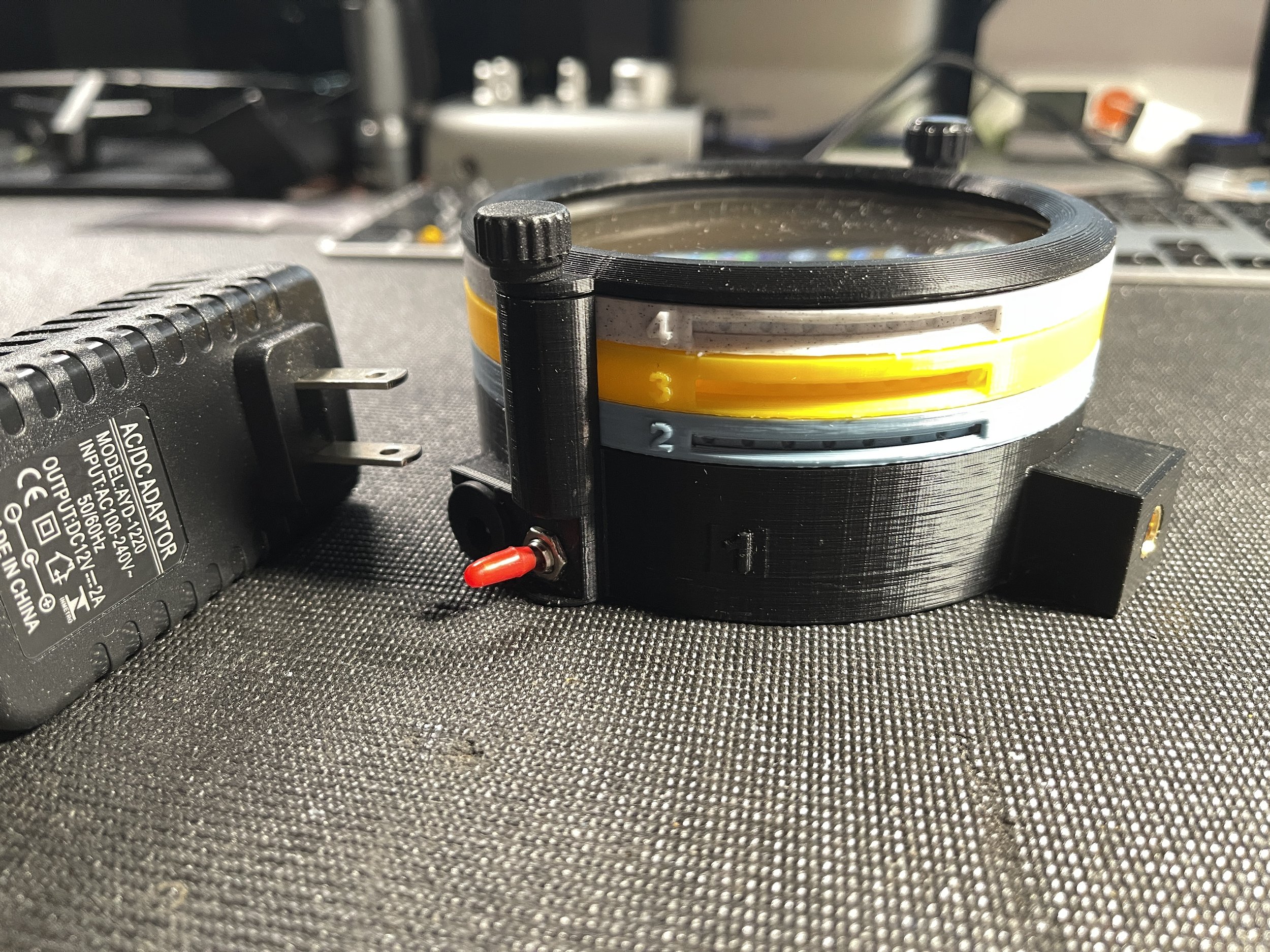
The viewer fully assembled and ready to use
This version of the platform represents a significant improvement over the first model in several ways. The viewer is smaller and lighter, but with a larger viewing area. It is designed to be used both in the horizontal position. With a new 1/4” 20 TPI mounting point, it can be secured to an articulating arm and positioned in almost any orientation. It is intended for viewing and/or photographing birefringent crystals grown on microscope slides and such slides can be locked into position on the specimen cassette to ensure they do not move or fall from the cassette during use. It contains a powerful light source and two layers of high quality linear polarizing material, along with a built-in diffusion layer and an empty filter cassette for addition of an optional retarder (wave plate), useful for viewing weakly birefringent material. I have included a brand new power supply, matched to the current requirements of the viewer. As an added bonus, I have prepared a sample slide (Acetanilide and ascorbic acid in methyl ethyl ketone) and installed it in the viewing position on the yellow specimen cassette. In the next section I will explain the purpose of each level and provide detailed instructions on how to use the device.

The colors are all wrong but fusion is not letting me change them
The viewer is made up of 4 separate levels, held in place by a cap ring secured with a pair of thumbscrews. The cap ring and levels 2-4 can be removed from the base (level 1) by removing the thumbscrews. Each level can only be mounted in one rotational orientation - do not try to force a level into the assembly without aligning the side pins with the receiving grooves on the upright extensions from the base.

The cassettes, in levels 2, 3 and 4 are freely rotatable through 360º by inserting the point of pen or pencil through the groove on the side of each level to engage with the circular depressions around the cassette perimeter. Each level and the cassette corresponding to that level are color coded and numbered. They should always be mounted onto the base (level 1) in the same order (2-3-4-Cap Ring).


Level 1 - the base layer - really black, not green
Level 1 - the base layer - color black - this layer contains the light source, wiring, 12V power socket and switch. When plugged in to the 12 volt power supply, the device is activated by showing the red switch. The Base Level also contains a cassette that holds a layer of diffusion filter material below and a layer of linear polarizing filter material above. The black cassette in the base is not accessible during use and it is not necessary to rotate this cassette during use. Avoid handling the level 1 cassette to prevent smudging, which could impact the quality of images photographed using this platform. This cassette may be removed to access the light source and wiring within the base layer. Not that the base layer has two vertical posts, with a brass insert at the top of each post. One post has a single square groove on its inward oriented face, while the other has a pair of round grooves on its inward facing surface. These grooves correspond to the vertical ridges visible on the perimeter of levels 2, 3, and 4. These insure proper orientation of the upper levels and prevent rotation off the level housings during rotation of the cassettes. The base level has a cubic prominence into which a brass thread insert has been installed. This allows for mounting of the assembled device on an articulating arm, which may be used to aid in positioning of the device during use. The insert accepts a standard 1/4”, 20TPI screw.

Actually pale blue, this is the 2nd layer, for a wave plate (optional)
Level 2 - the Retarder Level - Color Blue - this level is included for mounting an optional retarding filter or wave plate. The device is shipped without a retarding filter installed in the Level 2 cassette. A circular retarding filter with a diameter of 100 - 102 mm, may be installed in the cassette and held in place by 2-3 drops of hot glue, or other adhesive. Make sure the glue has dried completely before installing the cassette in the level 2 housing - failure to do so may prevent rotation of the retarder plate during use. During normal use, this level and its cassette may be left empty. The addition of a wave retarder is not required for viewing the majority of common birefringent crystals.

Actually yellow - both the housing and the cassette
Level 3 - the Specimen Level - Color Yellow - This level is designed to securely hold a glass microscope slide in one of two common sizes - 25mm x 75mm or 50mm x 75mm. The detents for each size slide are oriented perpendicular to each other, so that only a single slide may be mounted at a time.

Note the tiny retaining tabbe for each slide
At each end of the detents are either one or two tiny retaining tabs. To mount a specimen slide, the slide should be inserted beneath the paired tabs and lowered into the detent while gently squeezing the cassette on an axis perpendicular to the long axis of the slide. This will provide just enough clearance for the opposite end of the slide to fall into the detent, after which the lateral pressure is relaxed causing the single tab to engage with the slide, holding it firmly in position and preventing any movement of the slide during positioning or viewing. The slide is removed by gently squeezing the yellow cassette while raising one end of the slide (the end with a single tab) and pulling it forward, out of the slide holder. ***Care is required to avoid slide breakage. This cassette can also be rotated to adjust subject framing and composition.

Meant to be light gray - the second polarizer
Level 4 - The Analyzer Level - Color Grey - This level is used to house the second polarizer in the system. It is this filter that is rotated to achieve the desired level of cross polarization (the first polarizer is fixed). This cassette is also rotated using the tip of a pen or pencil, inserted into one of the round depressions on the circumference of the cassette. When the second polarizer is perfectly positioned, perpendicular to the polarizing axis of the first polarizer, all light will be extinguished except for that being refracted by the birefringent material. Note that this is the last layer at the top of the device and that it is prone to damage or the accumulation of dust and other debris. When not in use the device should be stored in a closed box to prevent damage to the polarizing film.

The top ring holds everything together
Level 5 - The Cap Ring - Color Black - this is not a functional level and serves only to secure all the lower levels within the device, allowing it to be positioned in any orientation without movement of the component parts. The thumb screws must be used to secure the device when in use. I have recently replaced the original screws with much shorter fasteners that allow rapid entry to the stack and access to the slide cassette. There should be no reason to dismantle the levels except to change the subject slide. The slide cassette is easily accessible and can be removed simply by removing the Cap Ring and the Level 4 housing. It is not necessary to remove the Level 3 housing to change the slide. Removal of the cassette will suffice.

A complex crystal photographed on the XP3BIO
Suggestions for use of the XP3BIO
Until you have some experience with the equipment, avoid using slides that still have unevaporated solvent present. Some of the solvents used could damage filters or the device itself.
Use only the provided 12 V power supply to avoid damage to the LED panel.
Do not over-tighten components attached to the brass insert on the front of the unit.
Never touch the filters - dirt and debris may lower image quality.
In some circumstances you may wish to further diffuse the light from the powerful COB light source. To do this cut a circle of 200mm diameter and place it on the shelf holding the Level 1 (base) filter cassette. Remember to remove when no longer needed.
Do not place anything other than a wave plate/retarding filter into the Level 2 (blue) cassette. A diffuser will lessen the effectiveness of the polarizing layer.
You may wish to add small rubber bumpers to the base and/or edge facings to prevent slipping.
Never leave the device turned on when it is left unattended. I have tested each unit and the COB LED does not produce enough heat to effect the housing or filters. But it is prudent to err on the side of caution.
The device works better when the cap ring is in place and thumbscrews are secured - without this locking layer it is possible to encounter difficulties when trying to rotate cassettes. Rotating the housing with the cassette may make it more difficult to maintain a particular level of cross polarization.
To view a specimen, remove both thumbscrews and lif off the cap ring. Carefully pull up on the second polarizer level (Level 4) and remove the housing and the cassette with polarizing filter. Then carefully remove only the slide holder cassette, leaving the housing in place. Gently squeeze the sides of the cassette to release the slide from the retaining tabs. Position one end of the new slide under the double tabs, then squeeze the slide holder on each side of the slide to raise the tab slightly and allow the slide to drop under the single sealing tab. Return the cassette to the yellow Level 3 housing. Replace the Level 4 housing taking care not to touch the polarizing filter and making sure that the ridges on the perimeter of the housing engage with the slots in the upright Level 1 alignment posts. Replace cap ring and tighten the thunbscrews before placing the viewer under your microscope or on your photography platform. Use an articulating arm secured to the viewer at the square mounting post if you wish to use the viewer at an unusual angle. Turn on the viewer’s light with the small toggle switch. Carefully rotate the yellow subject level cassette to the desired orientation for your composition. Then rotate the Level 4 cassette to maximize the polarizing effect. If no wave plate is being used it should be possible to completely extinguish all light except that which is being redirected by the birefringent material on the specimen slide

total extinction of ambient light when polarizing layers are 90º out of phase
In closing, thank you for purchasing this device! I am thrilled that you have sufficient faith in my “maker” skills to part with some of your hard-earned monies to acquire an XP3BIO. If you are happy with the device, please tell your friends, but if you are not, please tell me. I have made many improvements to the original design, but I am perfectly willing to believe that there are many more still to be made. If you think of one, please let me know!
I hope you enjoy using this invention as much as I have and I hope to see many of your crystal images in the future.
Allan